Remote Segment
As remote segment we understand a system (or a swarm of systems - coordinated or uncoordinated) that is deployed remotely from the site that controls its operation. Mostly such systems are used to do measurements or other tasks at locations that are either impossible or undesirable for the human operators to go.
The system has a rigid structure that houses a number of boards in a stacked configuration as shown below.
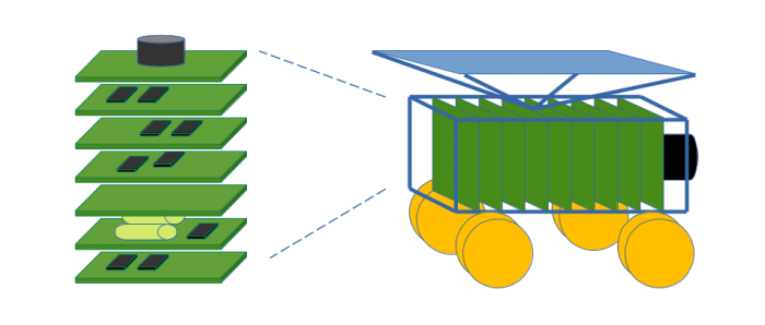
Each board typically as some certain functionality that it provides to the overall system, such as power supply, communications, navigation, and so on.
The specification of those boards is given in the LibreCube Board Specification. The board stack is interconnected through the PC/104-style inter-connector, with a total of 104 pins.
Our goal now is to define a modular, functional reference architecture, where specific boards can be easily replaced with newer or more performant versions without breaking compatibility. For this, we define a number of modules as shown in the figure below. We named the modules so that they reflect the generic functionality that is needed by most uncrewed vehicles, be it satellites, drones, or rovers. Not all functionality is needed by any system (e.g. a rover will not need a propulsion module, and not even every satellite needs one) - but whatever your platform needs to function, it should be possible to group it to one of those modules.
Note that we focus here on the platform functionality, that is, everything that is needed to support the operation of your system, like power, navigation, and processing. Anything that is specific to your mission, such as taking images with a camera, or drilling into rocks, is the payload part of your system and will be interfaced through the payload interface module.
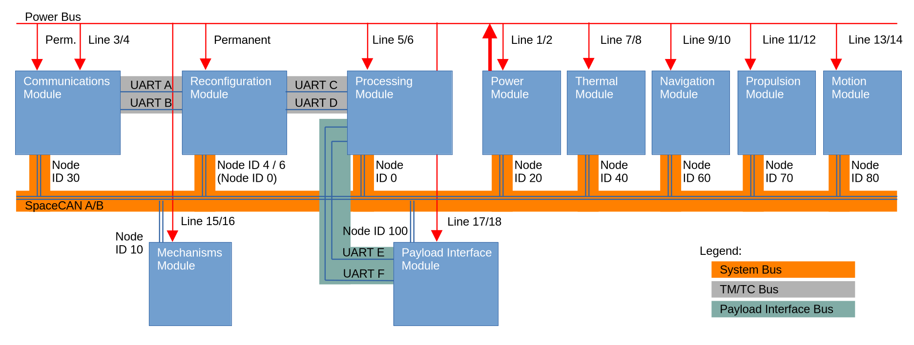
Each module is typically realized as a single board, but could also be made up from several boards and/or additional sensors and actuators with dedicated interfaces. For example, the motion module of a rover would be a wheel drive, and it will use additional cables to connect to the servo motors. But those dedicated interfaces are module-dependent and not part of the reference architecture. (So, you can later swap the wheel drive with a 6-leg spider walk motion module, without the need to change anything on the other modules.)
Busses
System Bus
We use SpaceCAN as system bus. The architecture follows a centralized layout, where one central node (the processing module) is in charge of controlling and monitoring the other subsystems. In SpaceCAN terminology, the processing module is the controller node, whereas all other modules are responder nodes. (An exception is the reconfiguration module, which can also act as controller node in case of contingency, as explained later).
The node ids for each module are fixed as shown. For most modules, although there is internal redundancy, only one bus interface is active at a time per module. Therefore, each module has a single, fixed node id. An exception is the reconfiguration module, which has two bus interfaces active in parallel (hot redundancy).
Note that lower ids, have higher priority on the SpaceCAN bus. Hence, if the thermal module is congesting the bus with data, the messages from processing module will be processed nevertheless as it has higher priority (it actually has the highest priority).
The full functionality of the SpaceCAN bus, in particular its redundancy concept is detailed in the SpaceCAN specification.
TM/TC Bus
The (redundant) telemetry (TM) and telecommand (TC) bus is used to:
- route commands received from external operator, received by the communications system, through reconfiguration module, towards the processing module for execution, and to
- route data generated and stored onboard, starting at the processing module, over reconfiguration module, down to the communication module, to be sent to the external operator.
The reconfiguration module sits in between to intercept and execute high priority commands, such as switching over from one processing module to the redundant one. It also produces high priority telemetry of the system, so that even in case of both processing modules being off, the operator gets an essential overview of the system state. If this functionality is not needed (for very basic systems), the communications module can be connected directly to the processing module.
Payload Interface Bus
The processor has a dedicated interface to the payload interface module for exchange of non-critical, high volume data. Typically, the payload generates lots of data (such as images from camera) and this data shall not be sent over the system bus, as it is not needed for monitoring and control of the system status. Such data will be sent of this dedicated, redundant UART bus.
Power Bus
The power bus supplies all modules with electrical power, at a voltage level of 5 Volt (while the maximum current that can be drawn from this power bus is dependent on the actual power module in use). If modules need different voltage levels, such as 3.3V (typically for microcontrollers) or 12V (such as for motors), then the modules need to generate this voltage level themselves (using DC/DC converter) from the power line. Most modules are connected to two switchable lines as shown in the figure. For example, the thermal module is connected to power lines 7 and 8. The lines are used to switch on the main or redundant part of the module, with either one on at a time (cold redundancy).
An exception are the receivers of the communications module and the entire reconfiguration module, both operated in hot redundancy and connected to the permanent (not switchable) power line. The interface and transmitters of the communication module are however cold redundant, and thus there is switchable power line 3 and 4 connected to it as well.
Finally, also the power module has a selectable nominal and redundant interface (line 1 and 2). Nonetheless, its main function is to supply the electrical power to the power bus, and this is the case independent of whether line 1 or 2 are on or off.
Modules
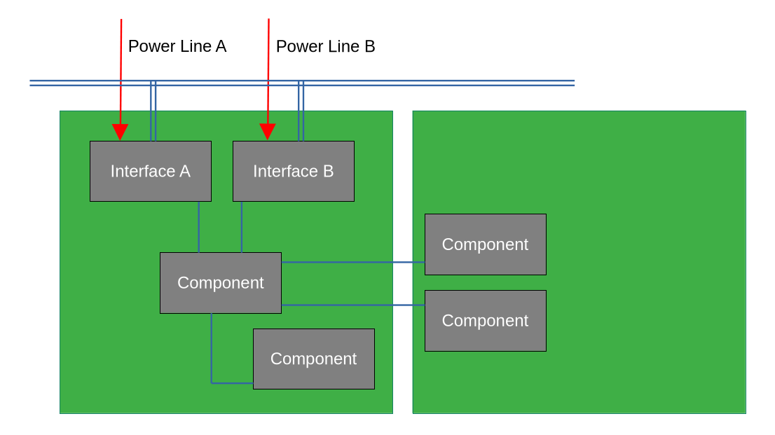
A module typically looks as shown in the figure below. It may consist of a single board or a stack of boards, but has only one, however redundant, interface to the system bus. The currently active interface (A or B) is selected through the power line, where only one line shall be powered at a time for a cold redundant setup. Whether the internal components of the module are redundant, is up to the module design, but it highly desirable. How this is realized is a design decision.
Note that if a module interfaces components that are off the board or hosted on another board, it must connect to it using dedicated interfaces. The specification of such interfaces is not part of the reference architecture. It can however use the pins of the PC/104 connector that are not reserved by the LibreCube board specification.
In the following, the reference design of the individual modules is presented. Note that this is a functional design; the physical realization is an implementation choice.
Communications Module
The reference design for the communications module is shown below. It interfaces to the SpaceCAN system bus, and the TM/TC bus (UART A and B). It receives power from permanent line and from switchable line 3 and 4. The powered line 3 or 4 defines whether interface A or B is active. Note that in the figure only the upper half of the board is shown, the lower part is essentially mirrored with appropriate connection to power line 4 and UART B and A bus, and SpaceCAN A/B.
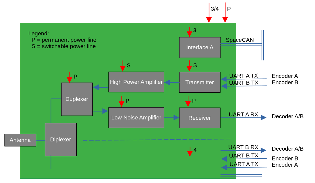
For the uplink, the module receives a signal (eg. over radio link) with its antenna (either single antenna with diplexer or two antennas, one per path) and amplifies it before reaching the receiver, where the data is demodulated as a bitstream. The receiver also decodes the bitstream to detect and extract the contained CCSDS telecommand frames, which are then sent through the TM/TC bus (UART). As can be seen, the receiving chain is hot redundant, with both chains operating in parallel.
For the downlink, CCSDS telemetry frames are received through UART A or B and then encoded and modulated, amplified to higher transmission levels, and finally radiated through the antenna. The transmission chain is cold redundant, only one chain powered at a time. Whether each downlink chain is sharing same power line as its interface, or if that is a separate switchable line is implementation dependent.
Reconfiguration Module
The reconfiguration module (RM) provides the essential commanding and monitoring capabilities, such that in case that the processing module has a serious problem (such as firmware corruption), the remote operator can issue high priority commands for rebooting the processing module or doing a reconfiguration (that is, switch to the redundant processing module). The RM is hot redundant, with both sides operating in parallel. Therefore, each interface has its own node id and can be addressed by the processing module at any time.
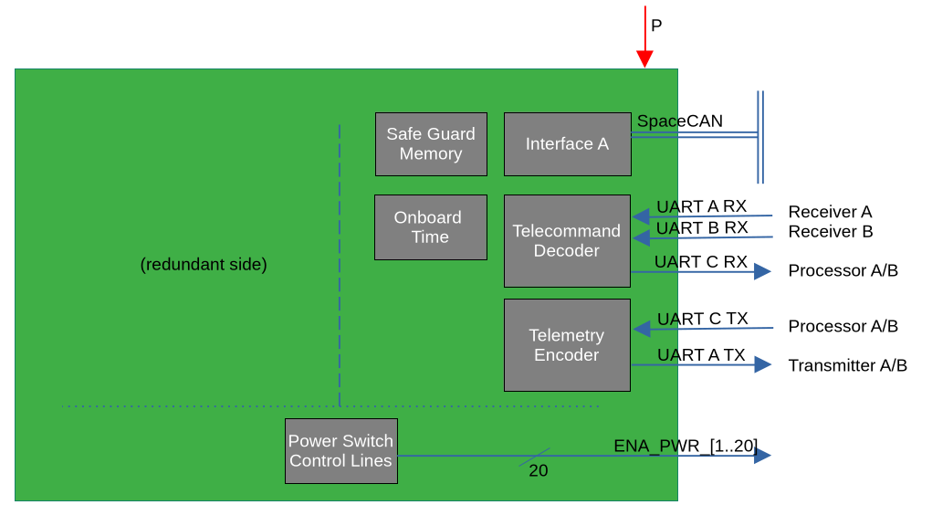
(Note that in the figure above the side B is omitted for simplicity. To complete it, all components except the lower part need to be mirrored and the UART line names swapped from A to B, and C to D.)
Each side of the RM hosts a safe guard memory (SGM) and an onboard time. The processing module (PM) can write essential context data to the SGM from time to time, such that in case of PM reboot, this data can be recovered. Similar for the onboard time.
The telecommand decoder receives CCSDS frames from both receivers and normally routes them forward to the PM via dedicated UART line. Only high priority TCs are executed directly by the TC decoder. Similar for the telemetry: it receives CCSDS frames from PM and routes them to the connected transmitter. It will also multiplex its own (low volume) essential telemetry frames into this downlink stream.
The power switch control lines block is a shared component between both sides. It is a latched unit that outputs the on/off signal for the system power lines.
Processing Module
The processing module (PM) is relative simple from a hardware point of view. The main components are the processor and the mass memory. The processor runs the onboard software, which takes care of numerous tasks, including telecommand and telemetry handling, platform and payload data storage, timekeeping, and monitoring and control of the other subsystems.
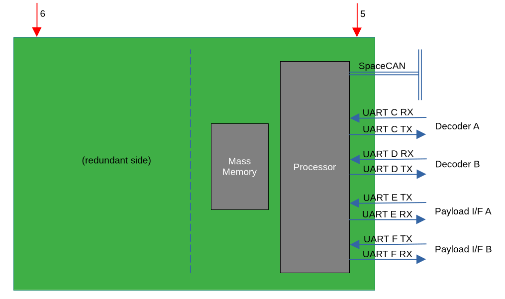
The PM is cold redundant, only one side is powered at a time. The figure above only shows one side, while the other side contains same components and interfaces. Either side is selected through dedicated switchable power line. The redundant side may be hosted on the same board or be a separate board.
Note: For a simplified system setup, where reconfiguration module is not used, and only a single processing module is used, the processor would connect directly to the communications module (that is, bridge UART A to C and B to D).
The UART E and F bus are used to connect to the payload interface, where one is used in nominal case and the other one as backup.
Power Module
The power module interfaces SpaceCAN with cold-redundant interface A and B, of which either one is active at a time. The interface is mostly for providing status information of the system. The power generation electronics are largely autonomous and continuously supply power.
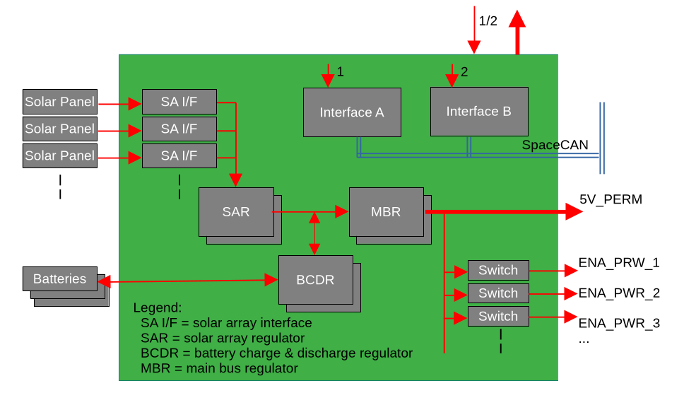
The input power from the attached solar arrays is conditioned at the solar array interface (either linear or with maximum power point tracking). They are then combined as input to the solar array regulator (SAR) that produces a stable output that is fed into the main bus regulator (MBR). Below sits a battery charge and discharge regulator (BCDR) that connects to the battery. It takes care of charging the battery when excessive power is available from the SAR. Otherwise, if insufficient power comes from SAR, the BCDR feeds the battery power towards the MBR. The MBR produces a stable output power, which is fed to the permanent power line and, through switches, to the switchable power lines.
Thermal Module
...
Navigation Module
...
Propulsion Module
...
Motion Module
...
Mechanisms Module
...
Payload Interface Module
...
Redundancy Concepts
Modules
...
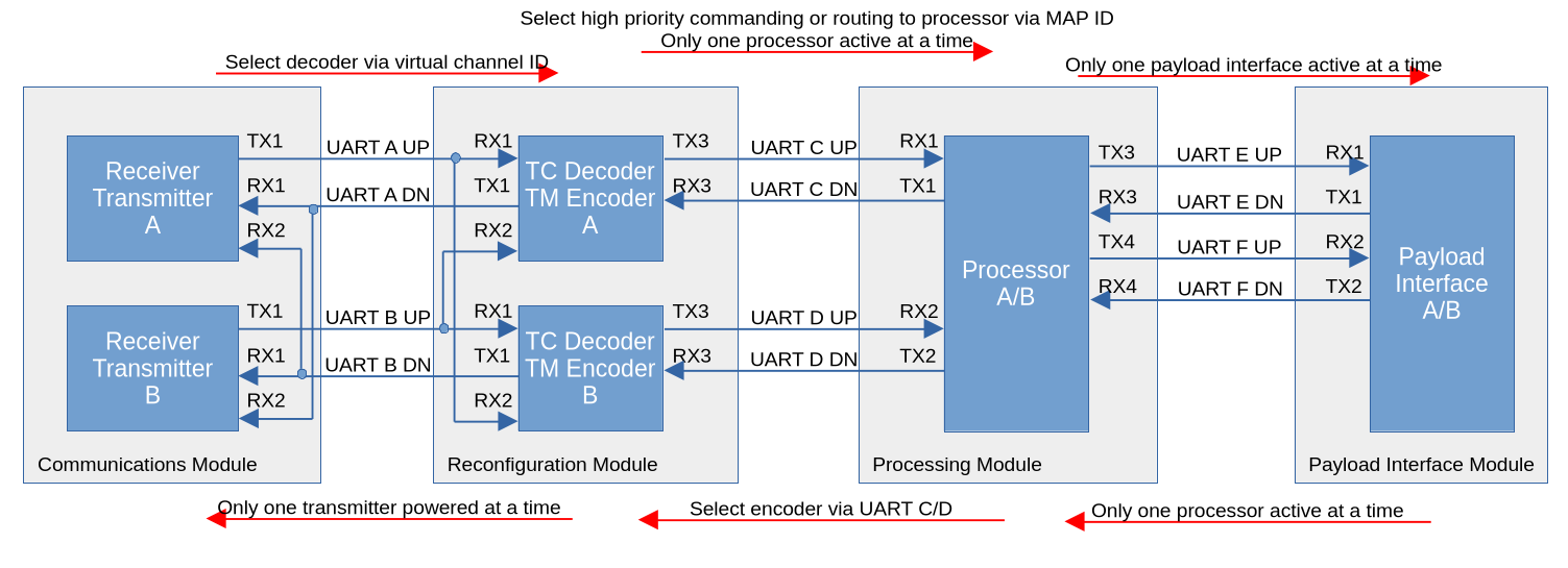
Telemetry and Telecommand Chain
- Receiver A is broken -> Both TC decoder still receive data from receiver B
- Transmitter A is broken -> Switch over to transmitter B
- TC decoder A is broken -> Processor receives data from TC decoder B (operator must switch VC ID)
- Processor A is broken -> Switch to processor B
- Payload interface A is broken -> Switch to payload interface B
Payload Interface
...
Communication Protocols
System Bus
...
TM/TC Bus
...
Payload Interface Bus
...